 Features
• Low Ellipticity Ratio
• Precision Electroformed
• Linear to Linear Polarization Versions
• Linear to Circular Polarization Versions
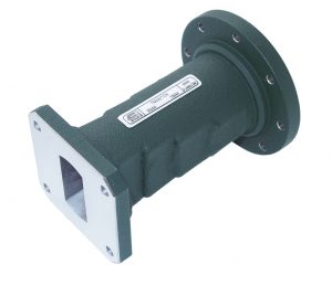
Each transition consists of a short length of rectangular waveguide and a stepped or tapered section leading into circular waveguide.
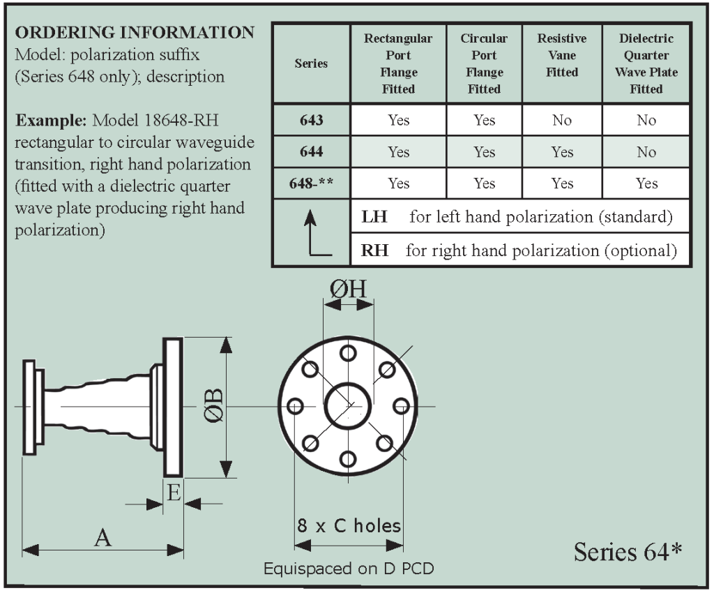
Models are available optionally fitted with combinations of rectangular port flanges, circular port flanges, resistive elements and dielectric elements. The standard rectangular flange types are listed in the table below. Alternative flange types can be fitted to order. The circular waveguide ports are fitted with the flange as detailed below or to customers requirements as other flange styles are available to special order.
The simple rectangular to circular waveguide transition will launch linearly polarized waves into the circular waveguide section (10643 to 32643). However, line reflections from the circular waveguide section may interact with the incident wave resulting in cross polarization.
If cross polarization is undesirable then the transition selected should be one fitted with a resistive film element to absorb the cross polarized waves (models 10644 to 32644).
For circular polarization, the transitions are fitted with resistive film element and have an extended circular waveguide section containing a dielectric quarter wave plate (models 10648 to 32648).
| Model | Frequency Range (GHz) | Waveguide | Overall Length A | Rectangular Port Flange Type | Circular Port Flange Dimensions | Weight (kg) Series 643/4 Only | |||||||
| WG | R | WR | Series 643 & 644 | Series 648 | B | C | D (PCD) | E | H | ||||
| 1064* | 2.6 - 3.95 | 10 | 32 | 284 | 241 | on request | 5985-99-083-1560/0010 | 146 | 6.9 | 132 | 11 | 73.91 | 4.3 |
| 11A64* | 3.22 - 4.9 | 11A | 40 | 229 | 178 | 330 | UDR 40 | 101 | 5.4 | 93 | 7 | 59.69 | 1.9 |
| 1264* | 3.94 - 5.99 | 12 | 48 | 187 | 140 | 249 | UAR 48 | 89 | 5.4 | 80 | 7 | 48.77 | 1.5 |
| 1364* | 4.64 - 7.05 | 13 | 58 | 159 | 120 | on request | UAR 58 | 89 | 5.4 | 80 | 7 | 41.42 | 1.1 |
| 1464* | 5.38 - 8.18 | 14 | 70 | 137 | 102 | 232 | UAR 70 | 76 | 4.4 | 60.3 | 7 | 35.81 | 0.8 |
| 1564* | 6.58 - 10.0 | 15 | 84 | 112 | 82.5 | 222 | UBR 84 | 60 | 3.2 | 52 | 7 | 28.58 | 0.3 |
| 1664* | 8.2 - 12.5 | 16 | 100 | 90 | 76 | 174 | UBR 100 | 56 | 3.2 | 48 | 6 | 23.36 | 0.25 |
| 1764* | 9.84 - 15.0 | 17 | 120 | 75 | 64 | 149 | UBR 120 | 56 | 3.2 | 48 | 6 | 19.35 | 0.2 |
| 1864* | 11.9 - 18.0 | 18 | 140 | 62 | 51 | 120 | UBR 140 | 50 | 3.2 | 41 | 6 | 16.1 | 0.1 |
| 1964* | 14.5 - 22.0 | 19 | 180 | 51 | 51 | 120 | UBR 180 | 50 | 3.2 | 41 | 6 | 13.25 | 0.1 |
| 2064* | 17.6 - 26.7 | 20 | 220 | 42 | 77.5 | 141 | UBR 220 | 50 | 3.2 | 41 | 5 | 10.93 | 0.1 |
| 2164* | 21.7 - 33.0 | 21 | 260 | 34 | 67.5 | 122.5 | UBR 260 | 50 | 3.2 | 41 | 5 | 8.76 | 0.1 |
| 2264* | 26.4 - 40.1 | 22 | 320 | 28 | 51.5 | 79.5 | UG-599/U | 44 | 3.2 | 35 | 3.5 | 7.24 | 0.06 |
| 2364* | 33.0 - 50.1 | 23 | 400 | 22 | 46 | on request | UG-383/U | Fixing detail as for UG-383/U | 5.8 | 0.06 | |||
| 2464* | 39.3 - 59.7 | 24 | 500 | 19 | 43 | 68 | UG-383/U MOD | 4.85 | 0.05 | ||||
| 2564* | 49.9 - 75.8 | 25 | 620 | 15 | 33.5 | 61.5 | UG-385/U | Fixing detail as for UG-385/U | 3.86 | 0.03 | |||
| 2664* | 60.5 - 92.0 | 26 | 740 | 12 | 28 | 51.5 | UG-387/U | Fixing detail as for UG-387/U | 3.12 | 0.03 | |||
| 2764* | 73.8 - 112 | 27 | 900 | 10 | 28 | 43 | UG 387/U MOD | 2.57 | 0.03 | ||||
| 2864* | 92.3 - 140 | 28 | 1200 | 8 | 28 | on request | UG 387/U MOD | 2.03 | 0.03 | ||||
| 2964* | 114 - 173 | 29 | 1400 | 6 | Dimensions available on request |
||||||||
| 3064* | 145 - 220 | 30 | 1800 | 5 | |||||||||
| 3164* | 172 - 261 | 31 | 2200 | 4 | |||||||||
| 3264* | 217 - 330 | 32 | 2600 | 3 | |||||||||


