 Features
• 0˚ – 180˚ Calibrated Phase Change Range
• Low Insertion Loss
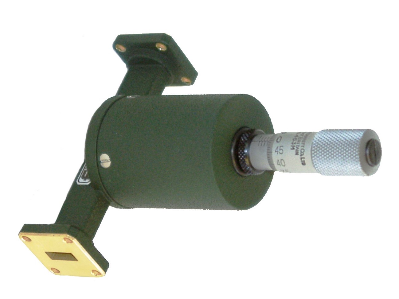
The Flann Series 060 / 061 instruments are fitted with low VSWR dielectric elements coupled to a precision micrometer drive. The micrometer indicates the relative position of the dielectric element in the waveguide.
All models provide a minimum of 180 degrees phase change and exhibit a very low insertion loss. The micrometer is fitted with a locking device which enables the adjusting mechanism to be locked at any setting. Two calibrations are provided at standard frequencies within each waveguide band. Alternatively the two calibration frequencies may be specified by the customer.
In the standard models 06060 to 22060 the dielectric element is introduced into the waveguide in a transverse manner. The standard 060 series instruments do not cover the top 15% of the waveguide frequency band.
When full band coverage is essential special models can be supplied at extra cost and are designated the 061 Series. For example, model 18061 is a full band model covering the frequency range 11.9 GHz to 18.0 GHz. Models 06061 to 22061 have VSWR better than 1.3:1 over the full waveguide band.
Models in the waveguide sizes WG23 (WR22) to WG32 (WR8) introduce the dielectric element into the waveguide via a slot on the centre line of the broad wall and are suitable for the full band operation as standard.
* For full waveguide band coverage order Model 061.
| Model | Frequency Range (GHz) | Waveguide | VSWR (better than) | Calibration Accuracy | Standard Calibration Frequencies (GHz) |
|||
| WG | R | WR | ||||||
| 06060* | 1.14 - 1.73 | 6 | 14 | 650 | 1.1 | 2˚ | 1.34 | 1.53 |
| 08060* | 1.72 - 2.61 | 8 | 22 | 430 | 1.1 | 2˚ | 2.02 | 2.31 |
| 10060* | 2.60 - 3.95 | 10 | 32 | 284 | 1.1 | 2˚ | 3.05 | 3.5 |
| 11A060* | 3.22 - 4.90 | 11A | 40 | 229 | 1.1 | 2˚ | 3.83 | 4.37 |
| 12060* | 3.94 - 5.99 | 12 | 48 | 187 | 1.1 | 2˚ | 4.62 | 5.31 |
| 13060* | 4.64 - 7.05 | 13 | 58 | 159 | 1.1 | 2˚ | 5.44 | 6.25 |
| 14060* | 5.38 - 8.18 | 14 | 70 | 13 | 1.1 | 2˚ | 6.31 | 7.25 |
| 15060* | 6.58 - 10.0 | 15 | 84 | 112 | 1.1 | 2˚ | 7.72 | 8.86 |
| 16060* | 8.20 - 12.5 | 16 | 100 | 90 | 1.1 | 2˚ | 9.63 | 11.07 |
| 17060* | 9.84 - 15.0 | 17 | 120 | 75 | 1.1 | 2˚ | 11.56 | 13.28 |
| 18060* | 11.9 - 18.0 | 18 | 140 | 62 | 1.1 | 2˚ | 13.93 | 15.97 |
| 19060* | 14.5 - 22.0 | 19 | 180 | 51 | 1.1 | 2˚ | 17 | 19.5 |
| 20060* | 17.6 - 26.7 | 20 | 220 | 42 | 1.15 | 2˚ | 20.63 | 23.67 |
| 21060* | 21.7 - 33.0 | 21 | 260 | 34 | 1.15 | 3˚ | 25.46 | 29.23 |
| 22060* | 26.4 - 40.1 | 22 | 320 | 28 | 1.15 | 3˚ | 30.97 | 35.53 |
| 23061 | 33.0 - 50.1 | 23 | 400 | 22 | 1.15 | 3˚ | 38.7 | 44.4 |
| 24061 | 39.3 - 59.7 | 24 | 500 | 19 | 1.15 | 3˚ | 46.1 | 52.9 |
| 25061 | 49.9 - 75.8 | 25 | 620 | 15 | 1.25 | 3˚ | 58.53 | 67.17 |
| 26061 | 60.5 - 92.0 | 26 | 740 | 12 | 1.25 | 3˚ | 71 | 81.5 |
| 27061 | 73.8 - 112 | 27 | 900 | 10 | 1.25 | 3˚ | 85.87 | 97.93 |
| 28061 | 92.3 - 140 | 28 | 1200 | 8 | 1.25 | 3˚ | 108.2 | 124.1 |
| 29061 | 114 - 173 | 29 | 1400 | 6 | Specifications available on request |
|||
| 30061 | 145 - 220 | 30 | 1800 | 5 | ||||
| 31061 | 172 - 261 | 31 | 2200 | 4 | ||||
| 32061 | 217 - 330 | 32 | 2600 | 3 | ||||
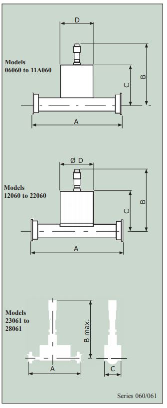
| Model | Dimensions (mm) | |||
| A | B Max | C | D | |
| 06060 | 1250 | 372 | 216 | 400 |
| 8060 | 850 | 242 | 157 | 151 |
| 10060 | 480 | 223 | 138 | 151 |
| 11A060 | 450 | 217 | 132 | 151 |
| Model | Dimensions (mm) | |||
| A | B Max | C | Dia D | |
| 12060 | 370 | 145 | 92 | 86 |
| 13060 | 340 | 141 | 89 | 86 |
| 14060 | 310 | 138 | 86 | 64 |
| 15060 | 240 | 132 | 83 | 64 |
| 16060 | 180 | 127 | 79 | 64 |
| 17060 | 180 | 125 | 78 | 64 |
| 18060 | 150 | 100 | 54 | 35 |
| 19060 | 125 | 97 | 52 | 35 |
| 20060 | 80 | 95 | 51 | 35 |
| 22060 | 70 | 100 | 49 | 12 |
| Model | Dimensions (mm) | ||
| A | B Max | C | |
| 23061 | 75 | 96 | 30 |
| 24061 | 75 | 96 | 30 |
| 25061 | 60 | 96 | 30 |
| 26061 | 60 | 96 | 30 |
| 27061 | 60 | 96 | 30 |
| 28061 | 60 | 96 | 30 |
| 29061 | Dimensions available on request | ||
| 30061 | |||
| 31061 | |||
| 32061 | |||
ORDERING INFORMATION
Model: Description
Example: Model 13060 Calibrated Phase Changer
The Full waveguide band model would be 13061


