
In high-frequency systems where precision and stability are paramount, the rotary vane attenuator (RVA) remains a vital tool. Used across industries ranging from aerospace and defense to telecommunications and scientific research, the RVA enables fine control of signal levels without compromising performance. In this blog, we take a closer look at the history, applications, and underlying principles of the RVA, exploring how it has evolved – and why is continues to be a critical component in advanced waveguide systems.
The rotary vane attenuator (RVA) has been an integral part of Flann’s offering for several decades. In fact, the precision RVA was one of the earliest products released by Flann (the company was founded in 1956) and has been considered a flagship product ever since.
From the early manual models, through the development of the first generation of WG26 programmable RVAs in the late 1970s, to the world’s first sub-millimetric WM570 RVA in the 2010s, Flann has always pushed the boundaries of this particular type of precision attenuator.
From a practical perspective, RVAs are often used in radar systems, microwave networks etc, as the inherently stable attenuation characteristics allow for highly precise signal adjustments.
For example, with a test bench setup, an RVA can be used to simulate precise atmospheric attenuation levels in a lab environment, for research and testing of antenna systems before field installation (related to real world considerations such as fade margin). Specialist field-use RVAs are also available.
To fully appreciate the value and performance of the RVA, it’s helpful to understand the underlying physics that makes its precision possible. While the applications highlight its versatility, the real ingenuity lies in how the device works at a fundamental level.
Essentially, the RVA attenuates a radio wave (or microwave) signal by rotating a resistive vane within the E-field of a circular waveguide. To convert from the standard rectangular cross-section of waveguide to circular, a further two resistive vanes are used within the rectangular-to-circular transition to reduce spurious modes and polarise the wave.
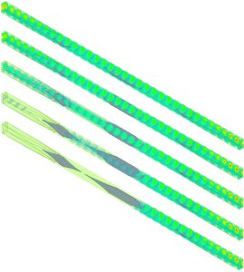
Figure 1: Simulation of the variation of the E-field through the rotary vane attenuator as the central vane changes angle.
The amount of attenuation depends on the angle between the normal of the vane and the original E-field vector, where the maximum and minimum occurs when the vectors are perpendicular and parallel to each other, respectively. Decomposing the E-field vector into an orthogonal basis, see figure 2, in an ideal RVA the E sin Θ component is absorbed by inducing a current in the resistive vane leaving just the E cos Θ component.
As the conversion back to standard rectangular waveguide consists of a further resistive vane, the process happens a second time absorbing a further E sin Θ component. This leaves the amount of E-field proportional to a cos² Θ term, with no dependence on frequency, and therefore a flat attenuation response across the waveguide band.
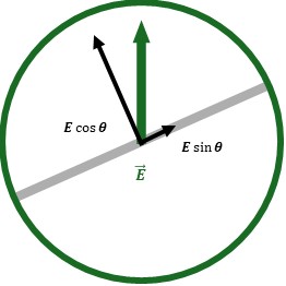
Figure 2: Decomposition of the E-field Vector
From its origin as one of Flann’s earliest innovations to its continued relevance in today’s cutting-edge systems, the RVA exemplifies the power of precision engineering. Its robust design and reliable performance make it indispensable for both laboratory research and real-world deployment. As technologies advance and system demands grow more complex, the RVA’s ability to deliver stable, predictable attenuation ensures it will remain an essential solution for engineers and researchers alike.